Steering Sensor
The Steering Sensor is used to implement local steering behaviour for your game's agents. When it is pulsed it will produce a Steering Vector. This is a velocity vector that the agent should match so it can reach targets of interest, while avoiding danger and potential collisions.
The sensor implements a combination of Context Based Steering and RVO (Reciprocal Velocity Obstacles). Following the Context Based Steering method described here, the sensor models its surroundings in a handful of spherical grids and chooses the direction that maximises a utility function. Some of these grids store candidate velocities calculated by the RVO method, these are velocities that won't result in a collision within a defined time horizon. The other grids store directions of interest or danger. Taken together, these grids decide the best direction to travel in and also the speeds that won't cause a collision.
The Steering Sensor can operate in a spherical mode suitable for flying agents, or a 2D planar mode for ground-based agents.
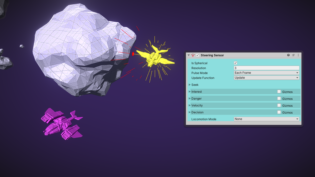
The Steering Sensor avoids the nearby asteroid while seeking the magenta spaceship
Output
The Steering Vector is accessible with the GetSteeringVector() method. This will be a velocity vector that can be passed to a locomotion system. If the built-in locomotion system is enabled then each frame the Steering Vector will be passed to that.
The candidate speed for a given direction can be accessed with the GetSpeedCandidate(direction) method. These will be calculated by the Velocity behaviour.
Directional Grids
To determine a Steering Vector the sensor first models its surroundings in a handful of Directional Grids. These are arrays of scalar values where each index is mapped to the surface of a circle or a sphere.
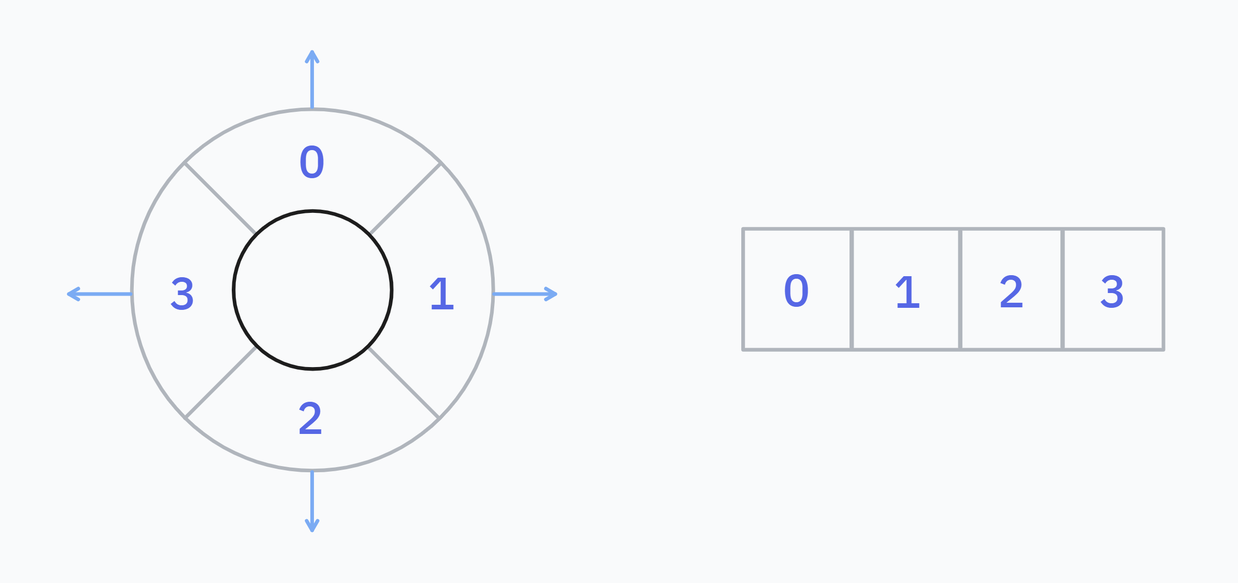 A low resolution directional grid with 4 cells on the circle. The cells are stored sequentially in memory such as on the right. Higher resolutions of grids would break the circle up into a larger number cells.
Each cell of the Directional Grid stores a value that describes some property of the spherical region it contains. The meaning of this value depends on the context. An interest grid for example would store a value in each cell measuring how interesting it is in that direction. A danger grid would store a value in each cell measuring how dangerous it is in that direction.
The Steering Sensor has four sub-behaviours: Interest, Danger, Velocity and Decision. Each behaviour produces one or more Directional Grids. The grids hold all the information needed by the sensor to decide the best Steering Vector. You can access the computed contents of these grids at runtime as well if you need it.
Steer Behaviours
Seek
Here you can choose a destination that the agent should reach. The behaviour doesn't have a grid of it's own, instead it adds values to the Interest grid. Therefore this is an extension of the Interest behaviour. There are a handful 'seek' modes available:
- Position - Causes the agent to aim towards a target
TransformorVector3position. TheArriveDistanceThresholdandStoppingDistanceproperties are relevant to this mode. You can query if the sensor has reached the destination usingSteeringSensor.IsDestinationReached. - Direction - Causes the agent to aim towards a
Vector3direction in world space. - Wander - Disables the 'seek' behaviour so it makes no changes to the
Interestgrid. - Stop - Will cause the agent to stop in place, no matter what is in the
Interestgrid or any other grid.
info
A Flee behaviour is also possible. Set the seek mode to Position and the Distance Offset to a large number. The agent will seek a position offset this distance away from the target.
warning
The sensor cannot plan a path through a complex level geometry, it's limited to only what it see's around it. For this you will need a pathfinding system to generate a path. This sensor can still be used to follow that path.
Interest
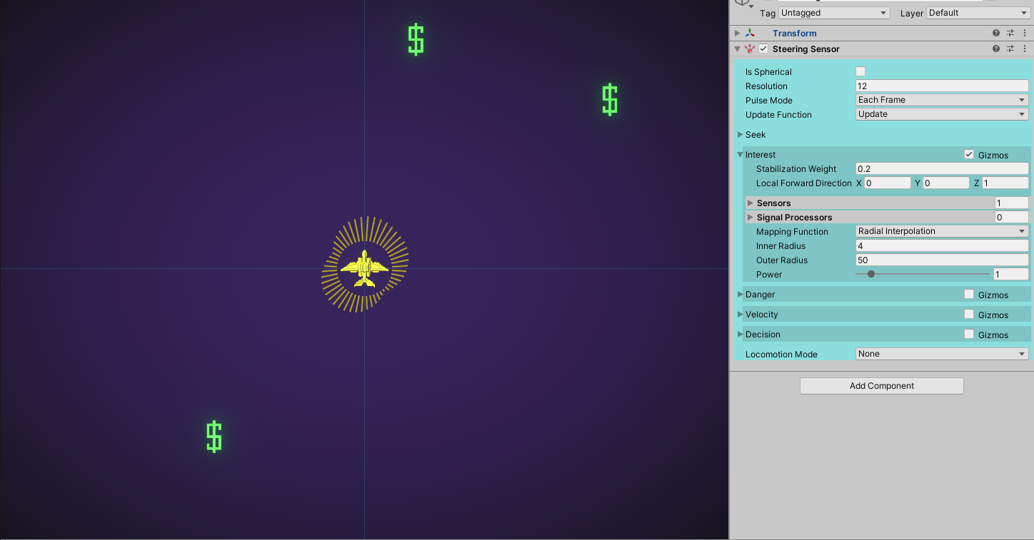
This behaviour constructs a directional grid that represents how 'interesting' a direction is. The greater the value in a particular direction, the stronger it will influence the agent to choose that direction. Interest values are linearly decayed from the angle to the target, which creates lobe shapes in the grid. Interest values are not additive when two or more targets are nearby, for each direction only the maximum interest is taken.
- Stabilization Weight - This helps to avoid the agent changing direction erratically. An interest vector of this length will be applied to the forward direction of the agent. Encourages the agent to keep its current direction.
- Local Forward Direction - The local direction that the stabilization weight is applied in.
- Sensors - A list of sensor references that detect interest targets. For each detected signal of each sensor in the list, interest will be applied to the grid in it's direction.
- Signal Processors - A list of Processors that will be run additionally on each signal from the sensor list. This is useful to filter out certain detections from the interest grid, or to modify the magnitude of interest a detection will have.
- Mapping Function - How to calculate the interest value for each detection. Possible values are Radial Interpolation which calculates interest by distance, or Signal Strength which uses
Signal.Strengthas the interest. - Radial Interpolation - Only relevant when Mapping Function is Radial Interpolation. Interest is interpolated from 1 to 0 by distance to the sensor. This property lets you set the interpolation range.
Danger
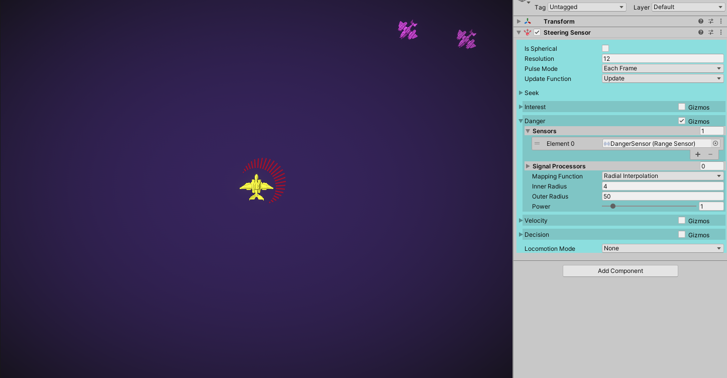
This behaviour constructs a directional grid that represents how 'dangerous' a direction is. It's effectively the opposite of the Interest behaviour. Danger in a particular direction will influence the agent to avoid that direction. Danger values are also linearly decayed from the angle to the target. Danger values are not additive when two or more targets are nearby, for each direction only the maximum danger is taken.
- Sensors - A list of sensor references that detect dangerous targets. For each detected signal of each sensor in the list, danger will be applied to the grid in it's direction.
- Signal Processors - A list of Processors that will be run additionally on each signal from the sensor list. This is useful to filter out certain detections from the danger grid, or to modify the magnitude of danger a detection will have.
- Mapping Function - How to calculate the danger value for each detection. Possible values are Radial Interpolation which calculates interest by distance, or Signal Strength which uses
Signal.Strengthas the interest. - Radial Interpolation - Only relevant when Mapping Function is Radial Interpolation. Danger is interpolated from 1 to 0 by distance to the sensor. This property lets you set the interpolation range.
info
The Velocity behaviour works better for obstacle avoidance, because it will cause the agent to speed-up and slow-down to avoid a collision giving more realistic results. The Danger behaviour works better for avoiding targets that are dangerous, but not necessarily on a collision course.
Velocity
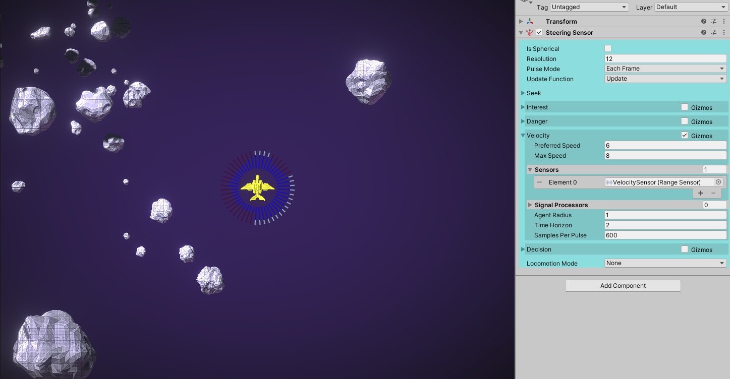
The Velocity behaviour calculates speed candidates over each direction in the grid. A speed candidate would avoid collisions with all nearby obstacles within a defined time window. The behaviour estimates the velocity of each obstacle by comparing their positions between sensor pulses. Speed candidates are calculated using the Velocity Obstacles algorithm.
- Preferred Speed - The speed that the agent should attempt to achieve if there are no obstacles.
- Max Speed - The maximum speed the agent can travel. The agent can speed up to this speed in order to avoid obstacles.
- Sensors - A list of sensors that detect velocity obstacles. Velocities are estimated for each detection by comparing their positions between pulses.
- Signal Processors - A list of signal processors that will be applied to the detections on the input sensors.
- Agent Radius - The radius of the agent used to predict potential collisions.
- Time Horizon - The sensor searches for speed candidates that avoids collisions within this time window.
- Samples Per Pulse - The number of potential speed candidates tested each time the sensor is pulsed. Speed candidates are searched for in a Unity Job.
Velocity obstacles are modeled as a sphere of radius Max(Signal.Bounds.extents). The sensor calculates two speed candidates for each direction in the grid: a lower candidate and an upper candidate. The lower candidate is chosen such that 0 <= lower <= preferredSpeed, and the upper candidate is chosen so preferedSpeed <= upper <= maxSpeed.
info
The speed candidates produced in the last pulse are stored on the sensor. They can be queried at runtime for a given direction using the sensor's API.
Decision
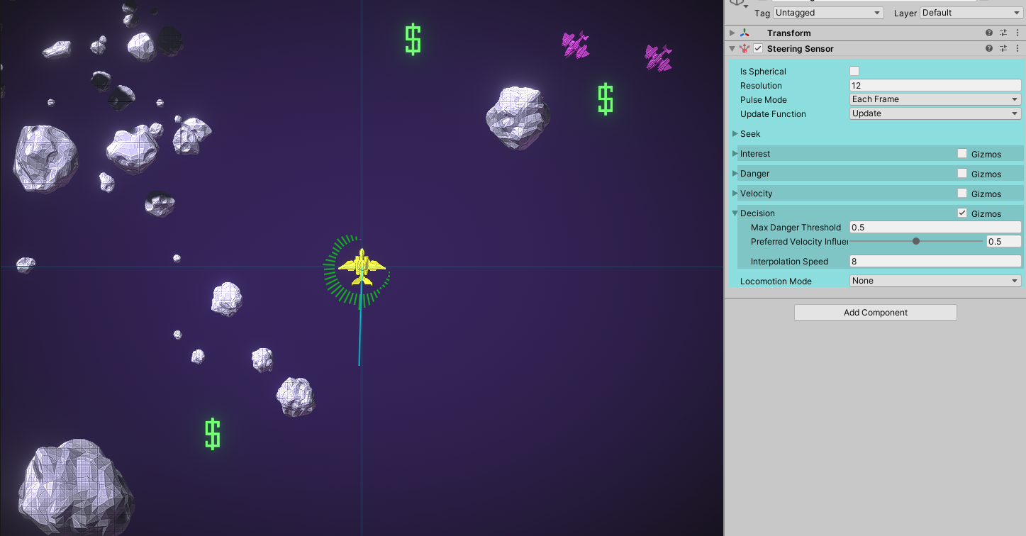
The decision behaviour takes grids of all the previous behaviours and produces an overall score for each direction. The Steering Vector produced by the sensor will be pointing to the direction with the highest score.
- Max Danger Threshold - Danger scores above this threshold will always repulse the agent no matter how much interest there is in that direction.
- Preferred Velocity Influence - How much the agent should favour directions that let it travel near its preferred speed. When this is greater then 0 the Velocity behaviour will steer the agent around obstacles.
- Interpolation Speed - The values in the decision grid are interpolated over time. When the sensor pulses a target decision grid is created, and the current decision grid is gradually changed to match the target. The speed that the change happens is controlled by this parameter. This is useful so the sensor can be pulsed on a fixed interval without erratic behaviour.
Locomotion
The steering vector is useful if you already have a movement system for your agent. Each frame get the vector and set your movement system to move in it's direction. Alternatively you can use one of the built-in locomotion systems. There are simple implementations for flying and ground-based agents.
info
The built-in locomotion system is very simple and not recommended outside basic use cases. In most cases you will want to use an external locomotion system and use the Steering Sensor to only calculate Steering Vectors.
Locomotion Mode
None by default, meaning locomotion is disabled and the sensor will only produce steering vectors. Can be set to one of:
- Rigid Body Flying - to control a flying
RigidBody, either kinematic or by forces - Rigid Body Character - to control a ground-based
RigidBody, either kinematic or by forces - Unity Character Controller - to control a
CharacterControllercomponent
The 2D version has only Rigid Body 2D which could work for a flying agent or a ground-based agent in a top-down game.
If a locomotion mode is selected you will see some extra properties that control it's max speed and acceleration.